Alright – here’s the no-nonsense, engineer’s checklist of the actual calculations you run when you design a pulsejet. Minimal romance, mAlright Simon — here’s the no-nonsense, engineer’s checklist of the actual calculations you run when you design a pulsejet. Minimal romance, maximum math — but I’ll let a little poetry seep in where it helps the thinking sing.
1) Define mission & constraints (inputs)
- Target static thrust TreqT_{\text{req}} (N)
- Flight speed V∞V_\infty (m/s) (0 for static tests)
- Ambient pa, Tap_a,\,T_a, altitude
- Fuel (LHV, stoich AFR), noise/size limits, materials temp limits
- Valved vs valveless (affects acoustics & timing)
2) Set the acoustic beat (the engine’s “heart rate”)
Pulsejets work because the geometry locks combustion to an acoustic mode.
Quarter-wave (straight/valved style)
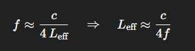
- Fundamental frequency (open–closed organ pipe):
f≈c4 Leff⇒Leff≈c4ff \approx \frac{c}{4\,L_{\text{eff}}} \quad\Rightarrow\quad L_{\text{eff}} \approx \frac{c}{4f}
- LeffL_{\text{eff}} includes end correction(s) (typically 0.3−0.6 D0.3{-}0.6\,D at the open end).
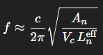
Helmholtz (valveless/annular, intake+tank+nuzzle)
Treat intake–combustor as a Helmholtz resonator:
where AnA_n and LneffL_n^{\text{eff}} are the neck (nozzle) area and effective length, VcV_c is combustor volume.
Design loop: pick a workable ff (often 40–250 Hz for small engines), estimate TmeanT_{\text{mean}} (between ambient and flame temp), compute LeffL_{\text{eff}} (or An,Vc,LnA_n, V_c, L_n) → set first-pass geometry.
3) Geometry ratios that usually matter
Use non-dimensional ratios so you can scale later:
- Combustor length Lc/DcL_c/D_c (commonly 2–6)
- Tailpipe length Lt/DtL_t/D_t (commonly 6–15)
- Area ratio At/AcA_t/A_c
- Intake area ratio Ai/AtA_i/A_t (valveless) — sets scavenging & backflow behavior
These couple back into (2) because they change LeffL_{\text{eff}} and TmeanT_{\text{mean}}.
4) Mass flow and time-averaged thrust
Time-average over a cycle: intake → burn → blowdown → refill.
Instantaneous thrust: T(t)=m˙e(t) Ve(t)−m˙i(t) Vi(t)+(pe(t)−pa)AeT(t)=\dot{m}_e(t)\,V_e(t) – \dot{m}_i(t)\,V_i(t) +\big(p_e(t)-p_a\big)A_e
For most small pulsejets at near-ambient exit pressure, the pressure term averages small; impulse is dominated by momentum terms.
Cycle-average: Tˉ≈m˙eVe‾−m˙iVi‾\bar T \approx \overline{\dot{m}_e V_e} – \overline{\dot{m}_i V_i}
At static test: ViV_i is into the engine (negative); in flight: add ram term +m˙aV∞+\dot{m}_a V_\infty.
Mass flow from continuity: m˙=ρAVwithρ=pRT\dot{m} = \rho A V \quad\text{with}\quad \rho = \frac{p}{RT}
Use separate states for intake (cooler, denser) and exhaust (hotter, lighter).
5) Exit velocity from energy balance
The blowdown converts pressure/thermal energy to jet kinetic energy.
A practical lumped estimate per cycle: Ve22‾ ≈ ηm ηc m˙f LHVm˙e\overline{\frac{V_e^2}{2}} \;\approx\; \eta_m\,\eta_c\,\frac{\dot{m}_f\,\text{LHV}}{\dot{m}_e}
- m˙f\dot{m}_f: fuel mass flow (kg/s)
- LHV: lower heating value (J/kg)
- ηc\eta_c: combustion efficiency (0–1)
- ηm\eta_m: mechanical/jet conversion efficiency (0–1)
Then Tˉ≈m˙e Ve‾−m˙i Vi‾\bar T \approx \dot{m}_e\,\overline{V_e} – \dot{m}_i\,\overline{V_i}
Solve iteratively with (4). This gives you a first-order link from geometry→acoustics→mass-flow→thrust.
6) Mixture & burn (don’t skip this)
- Stoichiometric AFR: AFRst\text{AFR}_{\text{st}} (by mass)
- Equivalence ratio ϕ\phi:
ϕ=(fuel/air)actual(fuel/air)st\phi = \frac{(\text{fuel}/\text{air})_{\text{actual}}}{(\text{fuel}/\text{air})_{\text{st}}}
Pick 0.8≲ϕ≲1.20.8 \lesssim \phi \lesssim 1.2 as a design range; richer mixes shorten ignition delay but raise temps.
- Adiabatic flame temperature TfT_f (look up or compute with a combustion solver). Your TmeanT_{\text{mean}} for acoustics will be between TaT_a and TfT_f depending on duty cycle and scavenging.
Fuel flow for a thrust target (back-solve): m˙f≈Tˉ Ve‾ηm ηc LHV\dot{m}_f \approx \frac{\bar T\,\overline{V_e}}{\eta_m\,\eta_c\,\text{LHV}}
You’ll refine once you have a better handle on m˙e\dot{m}_e and Ve‾\overline{V_e}.
7) Valve or no-valve timing (if valved)
If using reed/petal valves, make sure their dynamics play nice with ff.
- Valve natural frequency:
fn=12πkmefff_n = \frac{1}{2\pi}\sqrt{\frac{k}{m_{\text{eff}}}}
Design for fnf_n moderately above operating ff so the valve opens/closes crisply without flutter.
- Peak deflection & stress under pressure pulse Δp\Delta p:
σmax∝Δp a2t2\sigma_{\max} \propto \frac{\Delta p\,a^2}{t^2}
(aa=span, tt=thickness; use plate/beam formulas to size material and thickness.)
Valveless designs swap this for intake/nozzle area-ratio tuning to enforce phase-correct scavenging.
8) Intake/exit anti-backflow criterion (valveless sanity check)
You want fresh air in during low-pressure phase and minimal hot backflow during blowdown.
A simple screening metric is a Strouhal-like ratio comparing acoustic period to flow transit time: Stℓ=f LpathV‾path\text{St}_\ell = \frac{f\,L_{\text{path}}}{\overline{V}_{\text{path}}}
Keep Stℓ\text{St}_\ell =O(1)=\mathcal{O}(1) for the intake path so the flow can reverse when the pressure phase flips, but not so small that it free-wheels and short-circuits.
9) Pressure amplitudes & structural margins
Estimate peak chamber pressure rise from heat addition in (nearly) constant-volume fashion: p2p1≈T2T1≈1+ηc ϕ LHVcv T1⋅11+AFRactual\frac{p_2}{p_1} \approx \frac{T_2}{T_1} \approx 1 + \frac{\eta_c\,\phi\,\text{LHV}}{c_v\,T_1}\cdot\frac{1}{1+\text{AFR}_{\text{actual}}}
Use this Δp\Delta p for:
- Hoop stress (thin-wall):
σθ≈ppeak rt\sigma_\theta \approx \frac{p_{\text{peak}}\,r}{t}
- Thermal stress (through-thickness gradients):
σth≈E α ΔT1−ν\sigma_{\text{th}} \approx \frac{E\,\alpha\,\Delta T}{1-\nu}
Check fatigue: pulses per second =f= f; life targets in cycles ⇒\Rightarrow S–N with mean/alt stress from combined pressure+thermal loading.
10) Heat transfer & wall temperature
You must show the shell survives.
- Gas-side convection (internal turbulent):
Nu=0.023 Re0.8 Pr0.4,h=Nu kDh\mathrm{Nu}=0.023\,\mathrm{Re}^{0.8}\,\mathrm{Pr}^{0.4}, \quad h=\frac{\mathrm{Nu}\,k}{D_h}
- Heat flux:
q′′≈h (Tg−Tw)+ϵσ(Tg4−Tw4)q” \approx h\,(T_g – T_w) + \epsilon\sigma\left(T_g^4 – T_w^4\right)
- Through-wall temperature drop (1D):
ΔTwall=q′′ tksolid\Delta T_{\text{wall}} = \frac{q”\,t}{k_{\text{solid}}}
Confirm TwT_w < material limit with margin. If not, add film cooling, thicker wall, better alloy, or shorter duty cycle.
11) Noise estimate (because your neighbors will hate you)
Dipole-like source at ff with harmonics; far-field SPL at distance rr: SPL≈L0−20log10 (rr0)\text{SPL} \approx L_0 – 20\log_{10}\!\left(\frac{r}{r_0}\right)
Where L0L_0 comes from measured/empirical fits. Use this to check legal/operational limits.
12) Startup & stability margins
- Ignition energy vs mixture — ensure consistent light-off.
- Stability map: vary ϕ\phi and Ai/AtA_i/A_t; ensure the acoustic lock persists (no “chug” runaway or flameout).
- Altitude & speed sensitivity: recompute c,ρc, \rho and hence f,m˙f, \dot m, thrust.
13) Performance roll-ups
- Fuel flow: m˙f\dot{m}_f from §5
- Specific thrust: Tˉ/m˙a\bar T/\dot{m}_a
- Thermal efficiency (very rough):
ηth≈Tˉ V∞m˙f LHV(use V∞=0 to see why static tests “look” wasteful)\eta_{\text{th}} \approx \frac{\bar T\,V_\infty}{\dot{m}_f\,\text{LHV}} \quad(\text{use }V_\infty=0\text{ to see why static tests “look” wasteful})
- BSFC equivalent: m˙f/Tˉ\dot{m}_f/\bar T
14) Scale-up & similarity
Once one works, preserve:
- Frequency ff (or Strouhal fL/VfL/V)
- Area ratios At/Ac, Ai/AtA_t/A_c,\;A_i/A_t
- Non-dimensional heat-release parameter
- Re/Pr regime (stay turbulent internally)
Practical design flow (in order)
- Pick valved vs valveless and choose a target frequency band (noise + size + materials).
- Choose initial geometry from §2–3 (quarter-wave or Helmholtz).
- Assume ηc,ηm\eta_c, \eta_m and a ϕ\phi; compute m˙f\dot m_f, m˙e\dot m_e, Tˉ\bar T via §4–5.
- Adjust Ai/AtA_i/A_t, Lt/DtL_t/D_t, Lc/DcL_c/D_c to raise thrust while keeping the same ff.
- Check valves (if any) against ff and Δp\Delta p (§7).
- Run thermal & stress checks (§9–10).
- Iterate until thrust and temperatures meet constraints.
- Prototype, instrument (pressure transducers + thermocouples + load cell), and recalibrate your η\eta’s.
Guardrails (read this)
I’m deliberately not giving you build instructions, fuels, or dimension tables — pulsejets are extremely loud, very hot, and can be hazardous. Treat all of this as analytical scaffolding for safe, legal, instrumented experimentation, not a how-to for construction.